Mini Cooper S (R50/52, W11 B16AA) 2004
I became involved with this vehicle after the garage had been tearing their hair out, trying to get to the bottom of a power loss condition.
The vehicle had been in for a rear main oil seal replacement, due to an oil leak.
After completing the job, they had road tested the vehicle on an approximate six mile circuit, with no faults occuring.
The owner of the vehicle collected it and had to make a fairly lengthy journey. He found that after about twenty miles or so, the engine started to lose power and misfire. He returned it to the garage, not particularly happy.
They scanned it and found an odd trouble code recorded, (P1681: Electronic throttle monitoring, level 2/3, engine speed – calculation error), they also managed to get the car to misbehave, but only after getting it really hot and loading it considerably. When it started running badly, the throttle would shut down and the engine would misfire, but if they switched it off and let it cool down a bit, it seemed to be fine until really hot again.
They tried looking at the spark plugs, ignition coil etc.. but found no problems and even after replacing them temporarily, found no difference.
And so, over to me..
I had the fault demonstrated to me, after I had carried out some preliminary serial data analysis checks, with no obvious conclusions.
After witnessing the fault and recording the same fault code, I was confused by the DTC, as I had not come across it before and there seemed to be no information available to me, including from the manufacturer’s service information.
At first, I started looking at the throttle body operation, as I am aware of misfire conditions being generated with throttle body failures. However the throttle body worked perfectly well with actuation tests.
Then I thought about the wording of the trouble code and considered engine speed. And so I thought I would do some basic engine operation analysis with my trusty scope.
I started with a basic cam and crank signal check. I was not concerned about synchronisation, just whether there was any signal concerns.
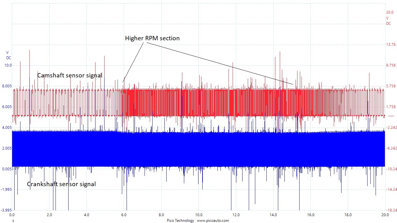
On first inspection, I didn’t see any obvious problems, although there was quite a lot of noise present and I did notice the crankshaft signal did not have very square edges.
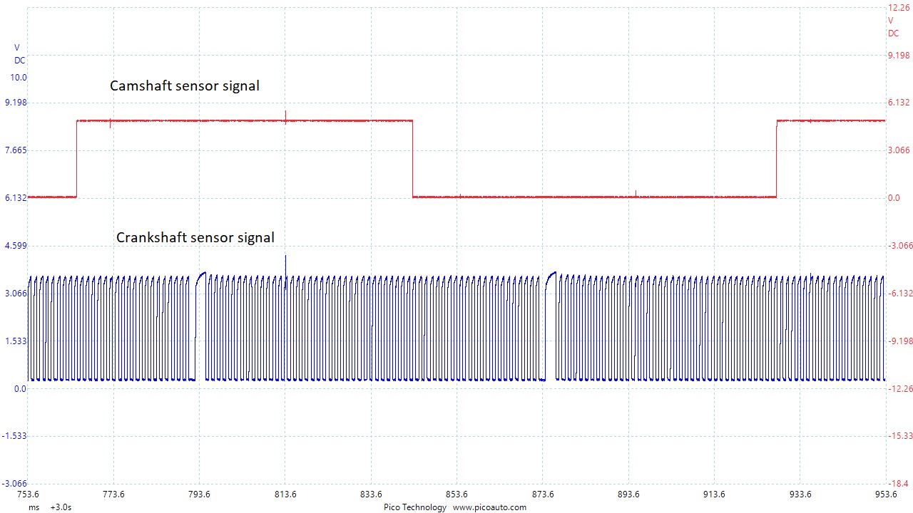
During the higher RPM section, the engine was clearly misfiring, so I was really looking for signal drop-outs. Even after zooming in on the crankshaft sensor signal, I didn’t really see an obvious fault. Maybe you will!
So I added in two more channels, to look at the ignition system. Now things became interesting, as you will see.
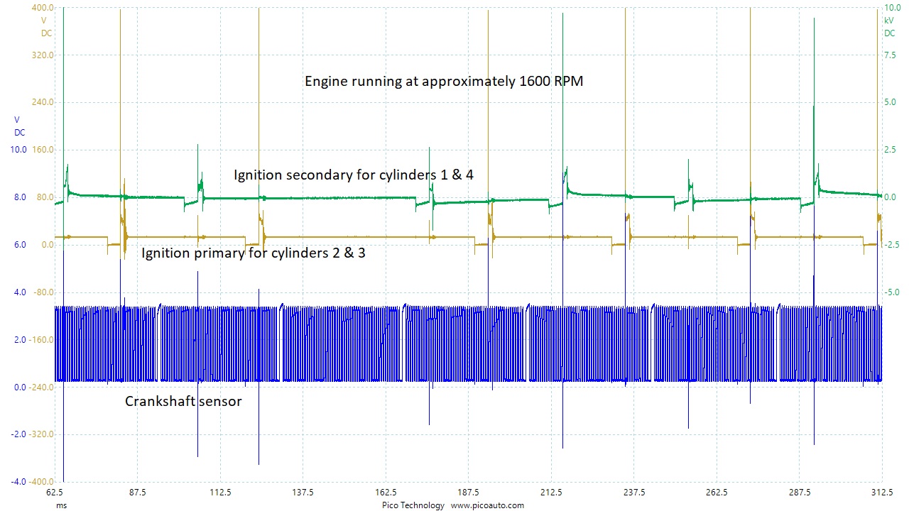
Look at the ignition firing signals, there are some missing. This made me really think about the crankshaft sensor dropping out reference positions, either by interference or missing segments. But clearly that did’t seem to be the issue here.
And so, it was time to step back and think about it. Sometimes you really have to ‘walk away’ to get a clearer picture.
Thinking about the fact, that there had been no complaint prior to the oil leak work and the lack of square definition in the crankshaft signal.
Then, suddenly it hit me! Look at the crankshaft signal and really analyse it.
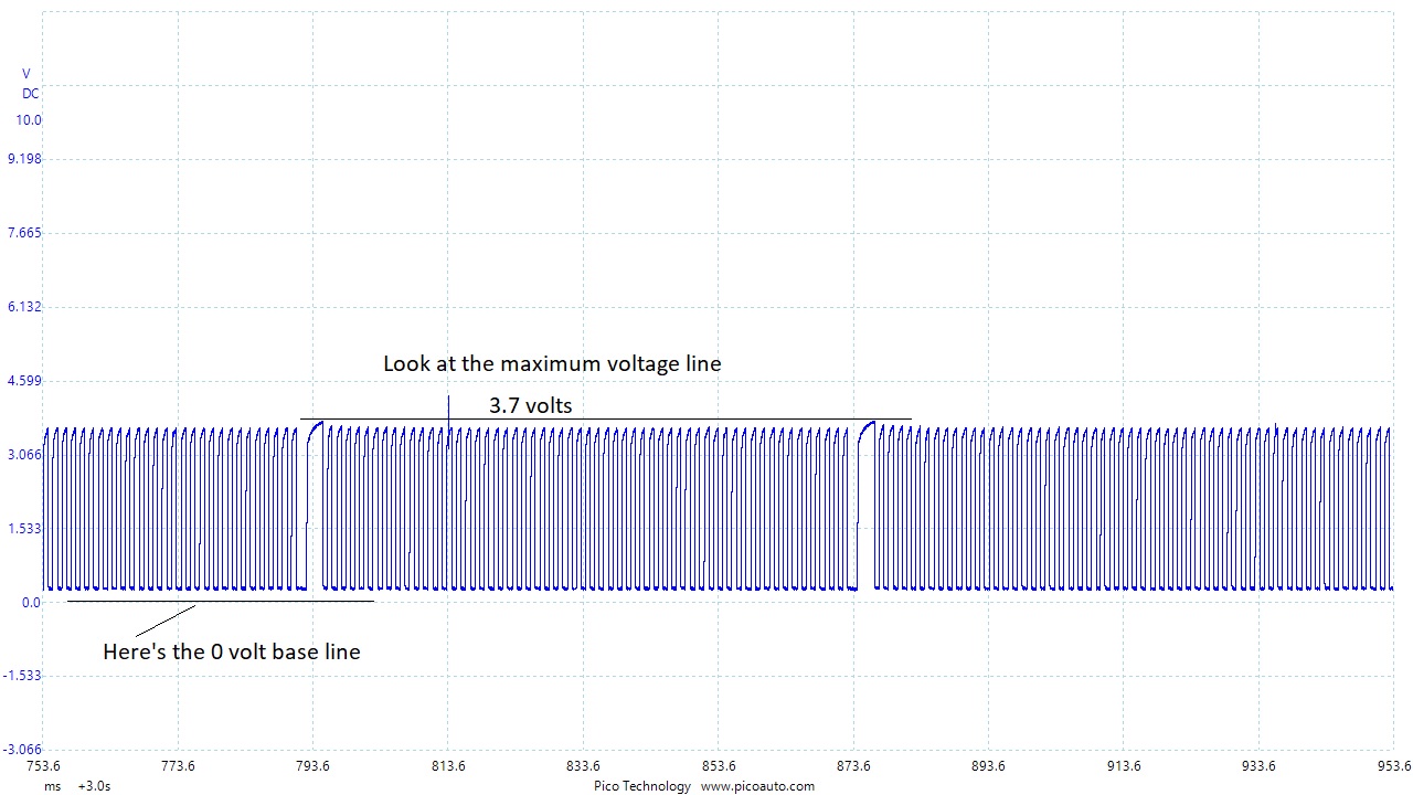
Sometimes the obvious is just not so obvious! This is a hall effect sensor that is powered by 12 volts, with a ground and signal. It is a ‘pull up’ sensor and so the signal voltage is created by the sensor. Typically, this type of sensor will produce a 5 volt signal and this one was not making it. Maybe the ECU could not clearly identify the reference mark at high speed. Unfortunately I didn’t have a known good sample to hand and the sensor is not very nice to access. I could just about get on the sensor connector to verify power and ground. The next step was to remove the sensor an inspect it, along with the wiring harness, as this was also very difficult to access.
The front of the car had to be removed and the sensor and harness were inspected, with no obvious or even subtle faults identified. Nothing for it; it had to have a new sensor.
A return visit after the job was completed, to verify the repair.
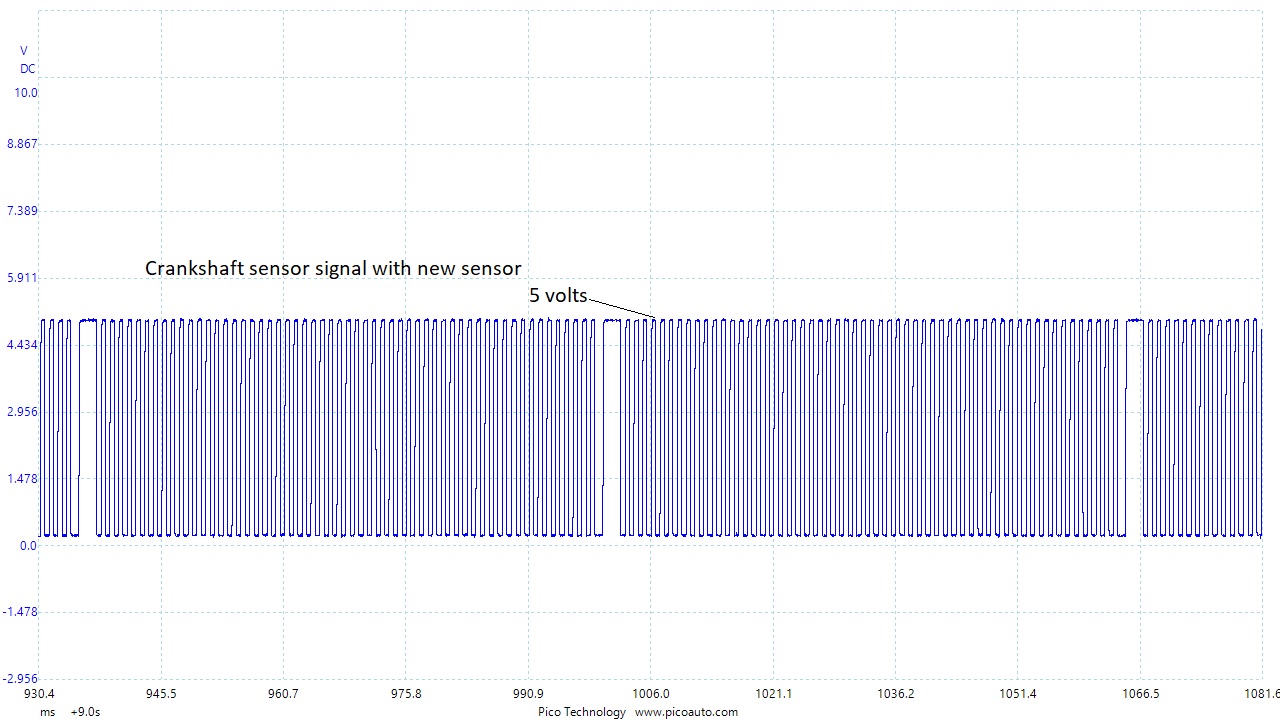
Look at the difference. The signal has nice square edges and runs at 5 volts.
The car was tested over a considerable length road test, with no problems.
So, the conclusion here is that the sensor was either damaged during the oil seal replacement operation, or that it was already impaired and ‘tipped over the edge’ by the operation, or that it was completely coincidental.. I don’t know, but it’s fixed now.
