Wheel speed sensors.
These sensors have been in use for a great many years now. The most commonly used were the inductive or VRS (Variable Reluctance Sensor) type, similar to that used as engine speed sensors and the like. There’s not much to say about these, as they are quite simple and there description is well covered by the engine sensor application.
So below I have included some basic captures.
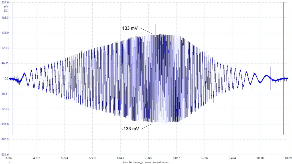
The above signal, came from a 1994 Jaguar XJS. It represents a good working signal, however it was coupled with signal anomaly. This is shown in the next image.
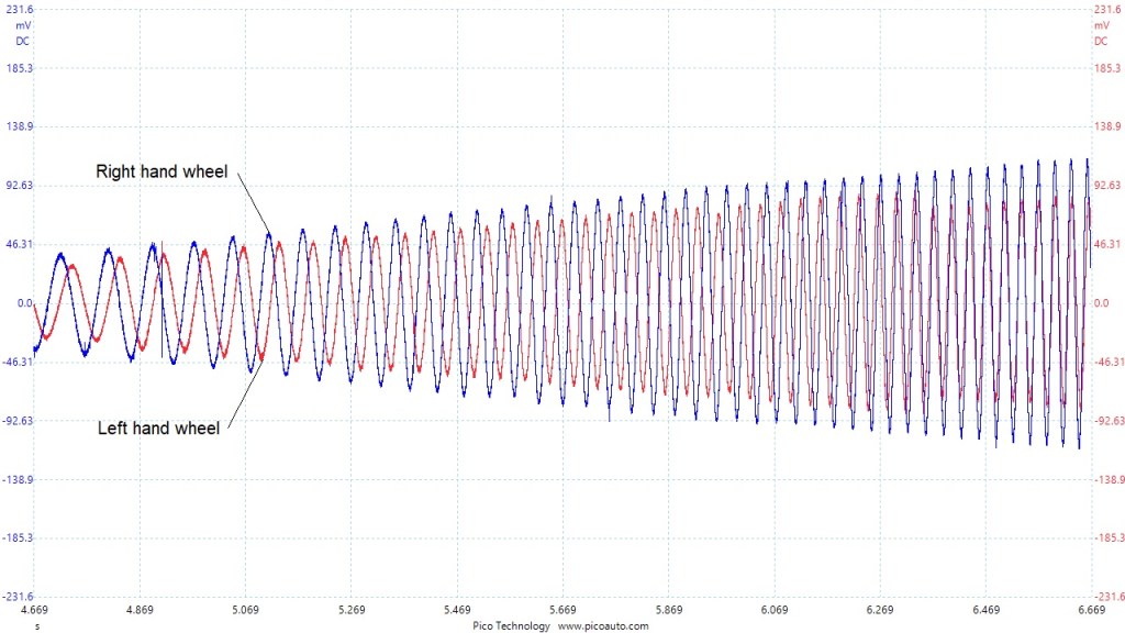
As you can see, the blue channel represents a good working signal, but the red channel illustrates the effects of an increased air gap. The sensor just required a little adjustment. Not a very exciting signal image, but always an interesting use of the scope. The scope was rigged up so that I could capture a sample whilst driving the car in a straight line. A straight line, should result in the road wheels turning at the same speed, thus producing a signal of the same amplitude. (As long as the wheels and tyres are even).
The following image represents another common fault.
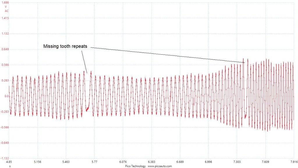
You can see the missing tooth from the rotor. This could be a missing tooth or contamination, blocking the magnetic field reaction. This fault usually results in low speed braking pedal pulsations, due to the ABS system acting as if the wheel would be approaching a lock condition.
More recently we see increased use of digital wheel speed sensors. These are pseudo ‘hall effect’ sensors. They are not actual ‘hall effect’ sensors, because they only use two wires. They are powered by the ECU and a portion of voltage reacts to the changing magnetic field. These sensors are used because they offer greater sensitivity, along with potential directional information. Vehicle stability systems use them, along with emerging technologies for greater safety systems.
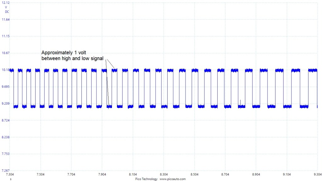
The signal rides at the top of the positive voltage. The sensors have a very high impedance circuit and so the voltage is altered very easily by magnetic interference.
In the following image, you can see how the directional information is achieved, if the sensor is equipped.
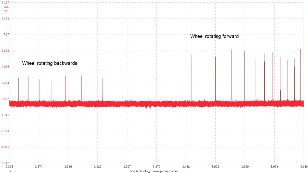
Each spike, represents a current ramp, as the signal changes. You can see how the current is approximately half the value when rotating backwards, compared to rotating forward.
This sample was captured using a milliamp clamp with a range capable of measuring very low current. The signal generated a maximum current of approximately 6mA.
Like the previous wheel speed signal, with a missing rotor tooth, identifying a rotor or reluctor segment as missing, can be challenging.
This image shows missing segments.
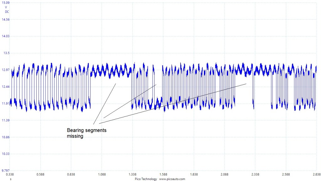
The image above, illustrates an obvious failure of the reluctor. However, consider the pattern when the wheel speed reduces, when the signal is either high or low. How do you know if a reluctor segment is missing or the rotation speed is slow? Remember the VRS sensor and how the speed is identified easily by the resultant amplitude, as well as the distance of the rising or falling slope. We don’t have that with digital.
If you can sample the signals with a uniform revolution speed, then it can be easy to spot a problem.
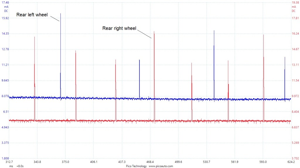
Take a look at this capture.
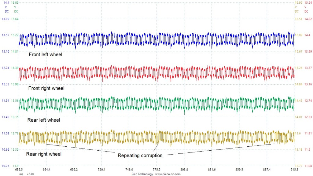
This is a classic failure. The rear right signal shows a repeating cycle of corruption, causing the traction control to become active on a BMW. The fault is caused by corrosion under the reluctor ring on the drive shaft.
What happens if you can’t get the vehicle to drive the wheels at a constant speed. Sometimes a tricky operation in a workshop.
Let’s look at the problem.

In this sample, I used a vibration sensor and a trigger source, fixed to the tyre. With this setup I was able to rotate the wheel, by hand, in the workshop and analyse the signal integrity.

As is always the case, you sometimes need to be a little inventive, when trying to find solutions.
In the following set of images, I’ve shown all the voltages and current for a standard wheel speed sensor, taken from a 2012 Peugeot. This vehicle is equipped with Bosch ABS 81. The wheel speed sensor does not support directional information.
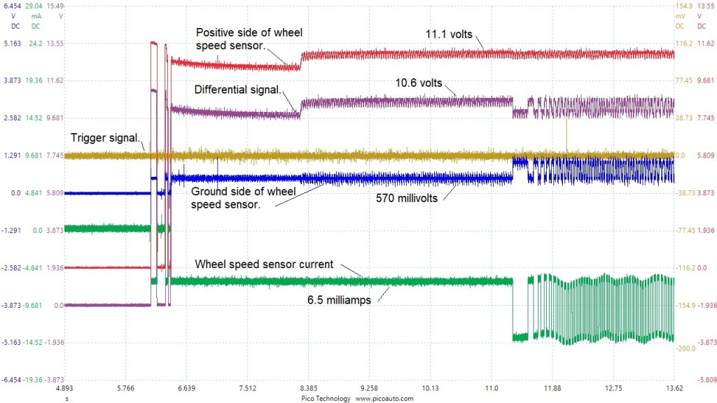
Channel Blue: +- 20V range. common chassis ground
Channel Red: +- 20V range. common chassis ground
Channel Green: +- 20mV range. Milliamp current clamp
Channel Brown: +- 200mV range. Piezo sensor
Channel Purple: Maths channel giving a differential measurement (Channel Red – Channel Blue)
I decided to capture this set of samples, as a question had been put to me about what voltages should be found, whilst looking into a fault.
I have not shown a circuit response with a fault present, but I can tell you that when a fault is present, the voltages will be present for a very short time. The ABS controller will shut down any output after detecting a fault.
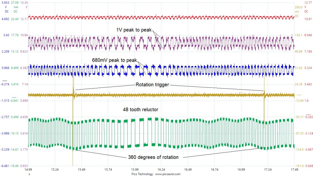
As before, I have used a Piezo sensor to generate a trigger reference. This makes it possible to identify 360 degrees of rotation, even with variable speed.
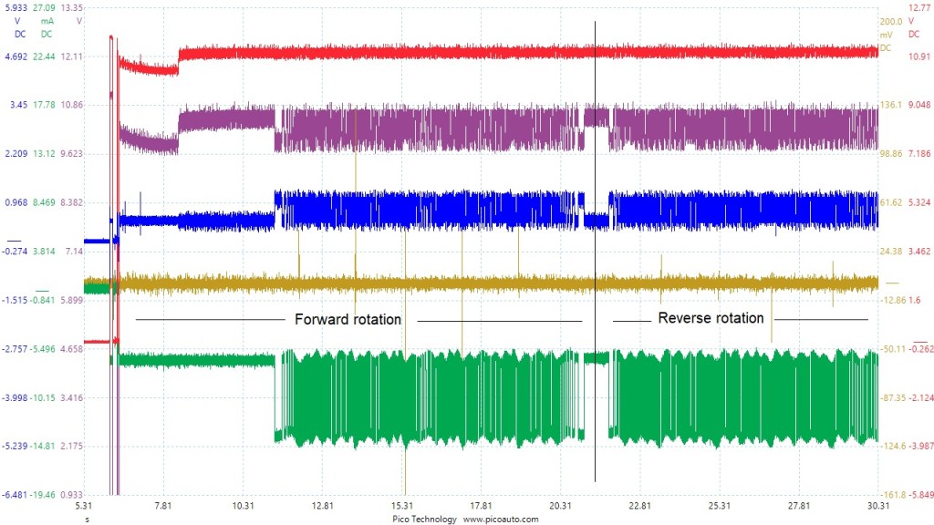
You can see how you don’t need to measure the current, in order to see the signal. The voltage signal is very small, the DSO can cope with that just fine. As you will see in the last image, this is not a directional sensor and so current is equal forwards and backwards.
This next set of images represents an interesting state.
They were taken from a 2007 Mercedes ML which had an over active traction control. Moving the vehicle slowly would result in the traction control activating, fairly aggressively. There were no DTC’s recorded. When you looked at live data for the wheel speeds, you would see the left rear wheel speed about half that of the others. After completing a circuit analysis of the sensors and finding no difference between any of them, I believed the reluctor to be the problem. (That’s a bearing, in this case). A new bearing was fitted. No difference!
I set the scope up on both rear wheel sensors, but only using voltage. I didn’t save the waveform, (sorry), the signal was very noisy and very difficult to analyse. I swapped to current. Take a look.
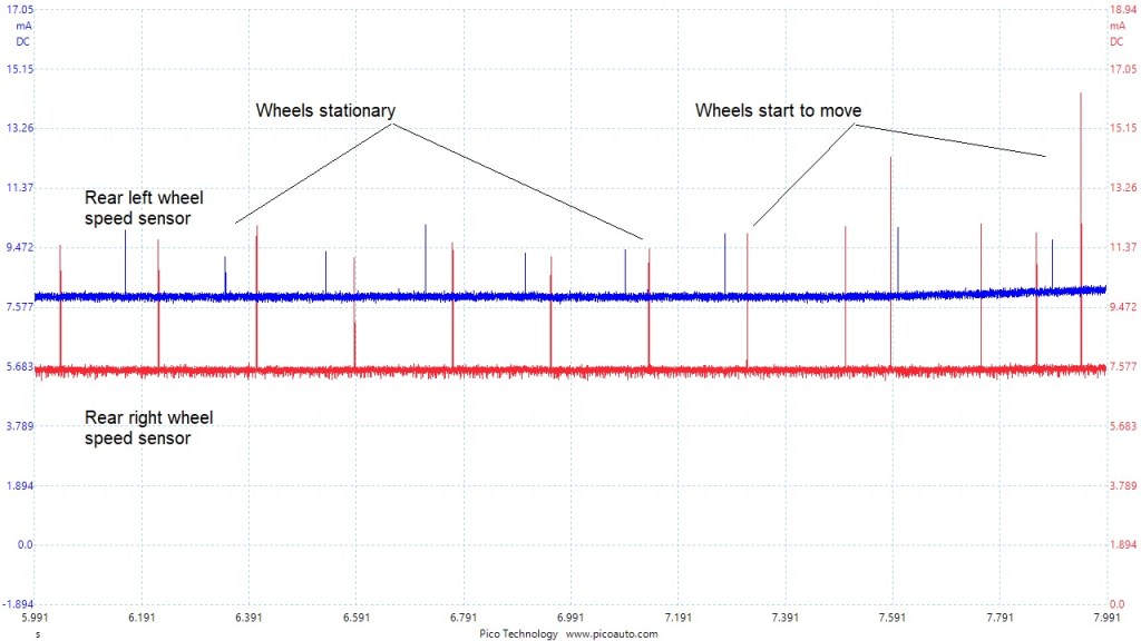
You can see, in the image, that the sensor signal has a current pulse present, when stationary. However, you can also notice the difference in amplitude between the blue trace and the red trace. Remember, both sensor’s circuit resistance is the same.
Now look at the signals with the wheels rotating.
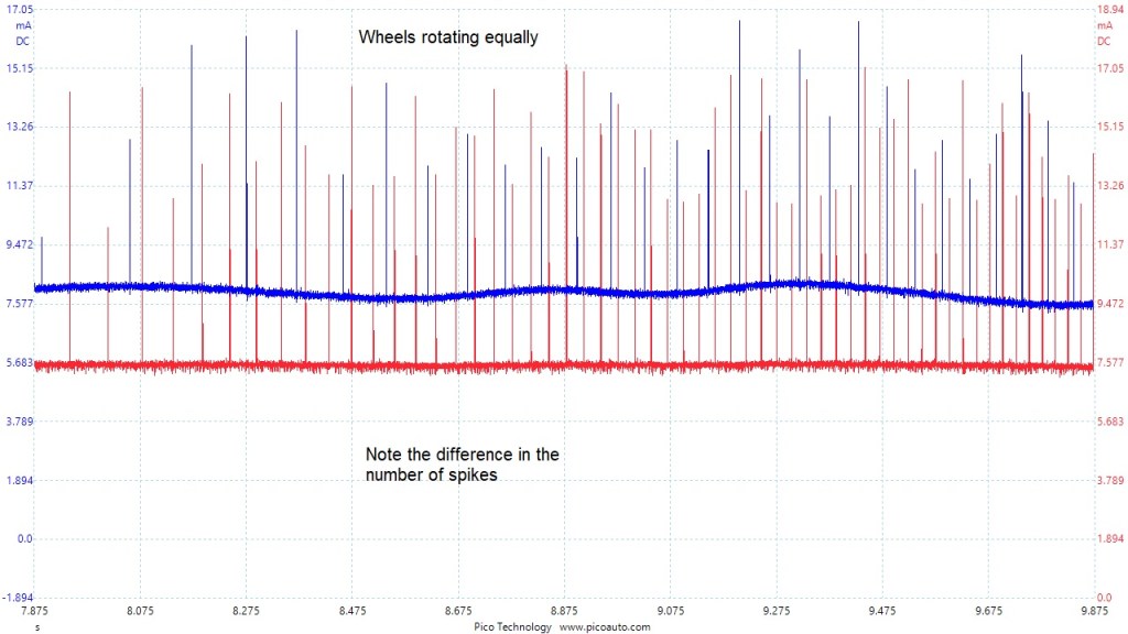
You’ll notice how there appears to be half as many blue pulses, as red. Is this due to reluctor segments or sensor operation? Take a closer look.
The other thing I noticed, is the current ramp profile.

Look at the difference in the current ramp profile. The amplitude doesn’t seem to be the important thing here, although I think it plays a part. The pattern seems to be far more important.
A new wheel speed sensor cured this fault. Just more stuff to think about! Maybe I’ll persevere and catch a voltage signal.
I thinks that concludes this set of images.
I’ll add more when I get them.
Air Suspension.
The image I have below is not a sensor from the vehicle, as it is just a general interest reference. It is the pressure output of the air suspension compressor fitted to a Land Rover Discovery 3. The image shows a good sample and a bad sample but not as fitted to the vehicle. This is a ‘short’ or ‘dead head’ pressure test.
I coupled my Pico 500X pressure transducer directly to the output port of the compressor. (Via a short hose connection. Note. The hose connection was not sealed perfectly and I could hear some pressure escaping, whilst testing the new unit. Consequently, the sample shows a minimum pressure output. There was no air escaping from the bad compressor sample).
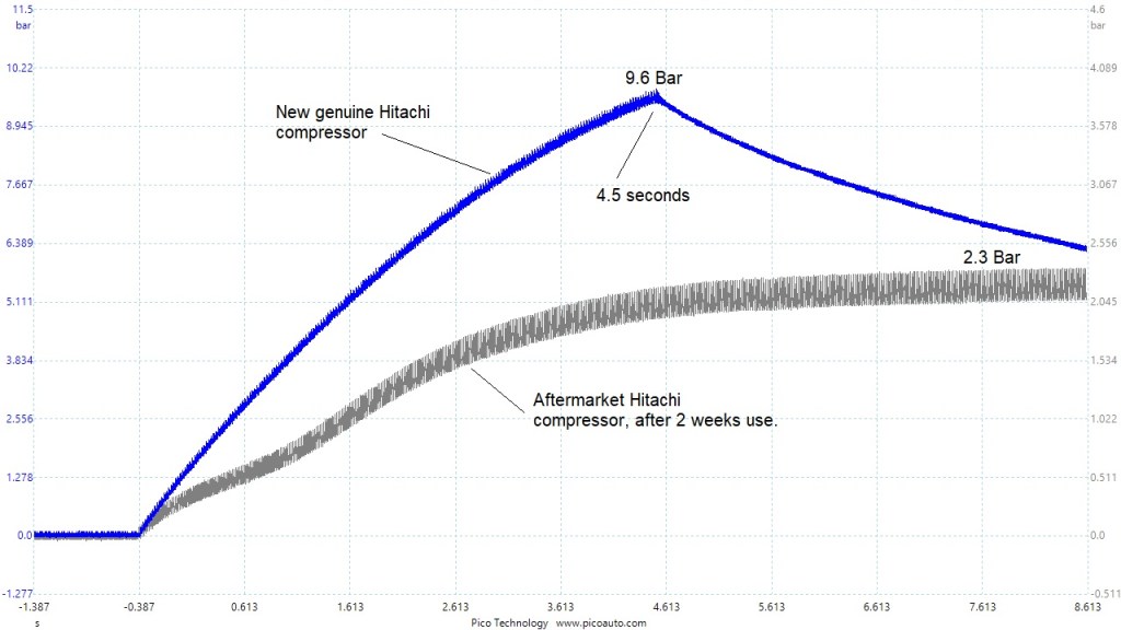
These samples were captured, using the actuation test facility in the scan tool.
The aftermarket compressor, was the second unit fitted with the same results. The new, genuine, unit is still good after several weeks use.
