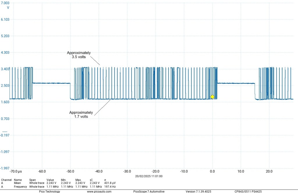
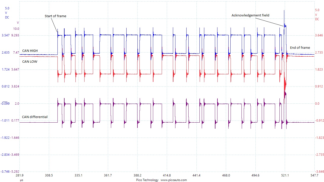
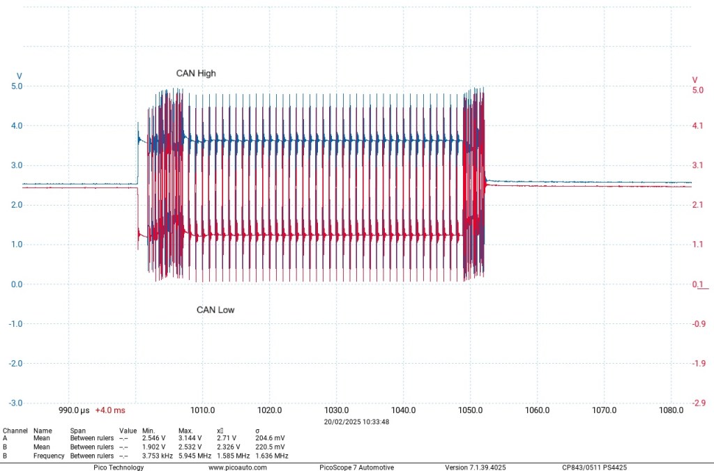
This image shows a high-speed CAN, (Controller Area Network), data bus signal. This type of CAN signal can run up to 1 mbit/s depending on the physical length of the circuit. I have included a ‘maths’ channel to show the differential voltage at 0 to 2 volts, which is normal. The ‘maths’ channel can be useful when testing CAN, because it cancels out any noise that may confuse real-time analysis. The twisting of the wires means that any interference that takes place on one wire, will take place on the other.
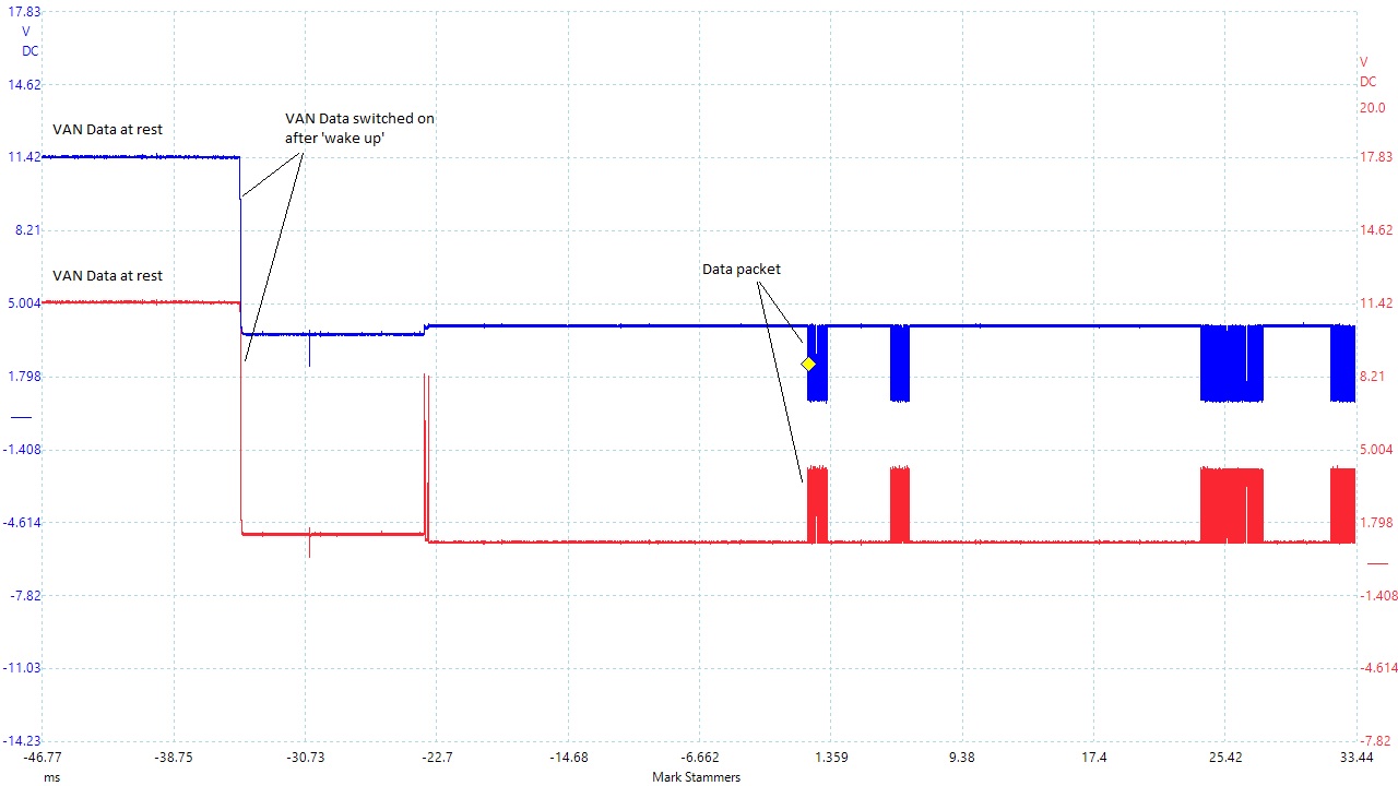
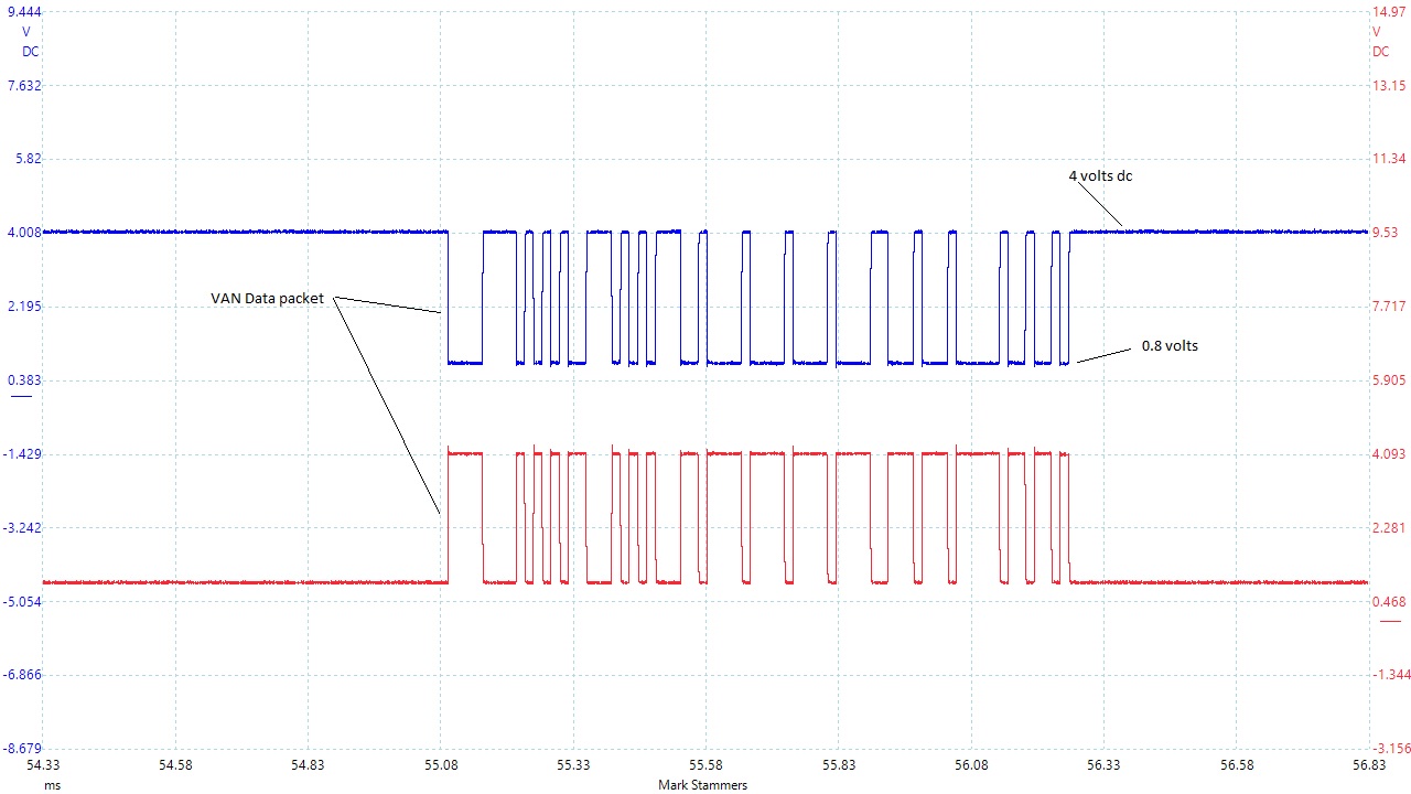
The next couple of images are of the ‘PSA’ (Peugeot / Citroen) proprietary ‘VAN’ (Vehicle Area Network), system. They are taken from the ‘VAN Body 2’ network, which is responsible for the door modules etc. You can see that when the network is dormant, it sits at just below battery voltage. When a ‘wake up’ signal is sent to the system, the voltage level drops to 0 to 4 volt signal. In fact it is closer to 1 to 4 volts. Unlike the Bosch High speed CAN system, the VAN does not use a differential signal, but instead it uses 2 lines of mirror image data. It is fault tolerant and can run with only 1 line operating, although in a downgraded mode, similar to that of the Bosch Low speed CAN. It also utilises the twisted pair interference suppression method of wiring. It does not have ‘end line’ termination resistors. This system dates back to the early 1980’s and is therefore a pretty slow system. The network illustrated here is a 62,5 kbit/s network. The faster VAN Comfort network, responsible for audio and navigation etc. runs at 125 kbit/s, but has exactly the same system operation. It started being phased out around 2005 and replaced by the more commonly used Bosch Low and Intermediate speed CAN.
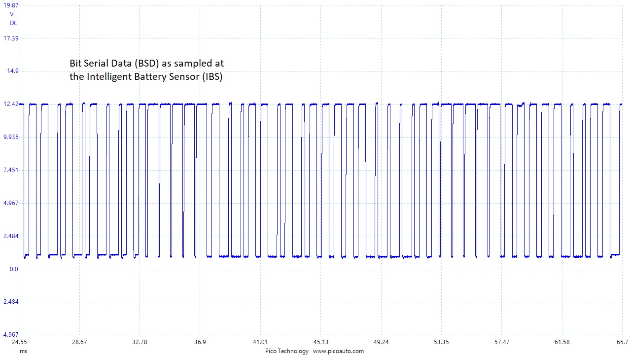
This image is of the BSD (Bit Serial Data), communication line for the pre-heat relay, alternator and intelligent battery sensor fitted to BMW vehicles.
It is a battery voltage signal that runs at approximately 1kHz.
LIN data bus
This sample is taken from a LIN controlled alternator, (seen in the casefile section).
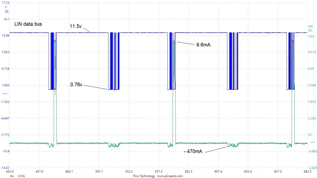
This is a zoom view of a 20 second screen sweep. That means it is not as high resolution as it could have been.
The current signal, (green), illustrates the bi-directional function of the data.
This next image is a closer look.
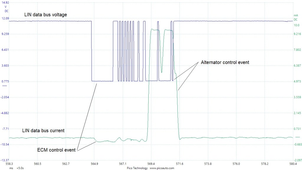
Because the ECM is responsible for providing the LIN signal, it takes very little current to switch the voltage from high to low. The alternator has to pull the voltage signal low and so requires more effort.
FYI: This LIN data signal runs at an average of approximately 300Hz, with a peak data rate of about 9.6KHz, and I would describe it as an approximate 12v signal.
The specification for LIN is 19.2KBits/s maximum.
The following serial date image is from a 2017 VW Touareg Active Cruise Control (ACC). It is a FlexRay physical layer. I have only measured the network with one channel, as I only had a single high frequency sample probe and I didn’t think to do a differential measurement at the time. I didn’t realise this system used FlexRay and so was testing for a regular CAN signal. I found what looked like a corrupt CAN as shown:
As you can see, the image looks a mess. I used standard scope test leads (1:1 standard length).
Next is the High side data layer, measured with a High frequency 10:1 probe
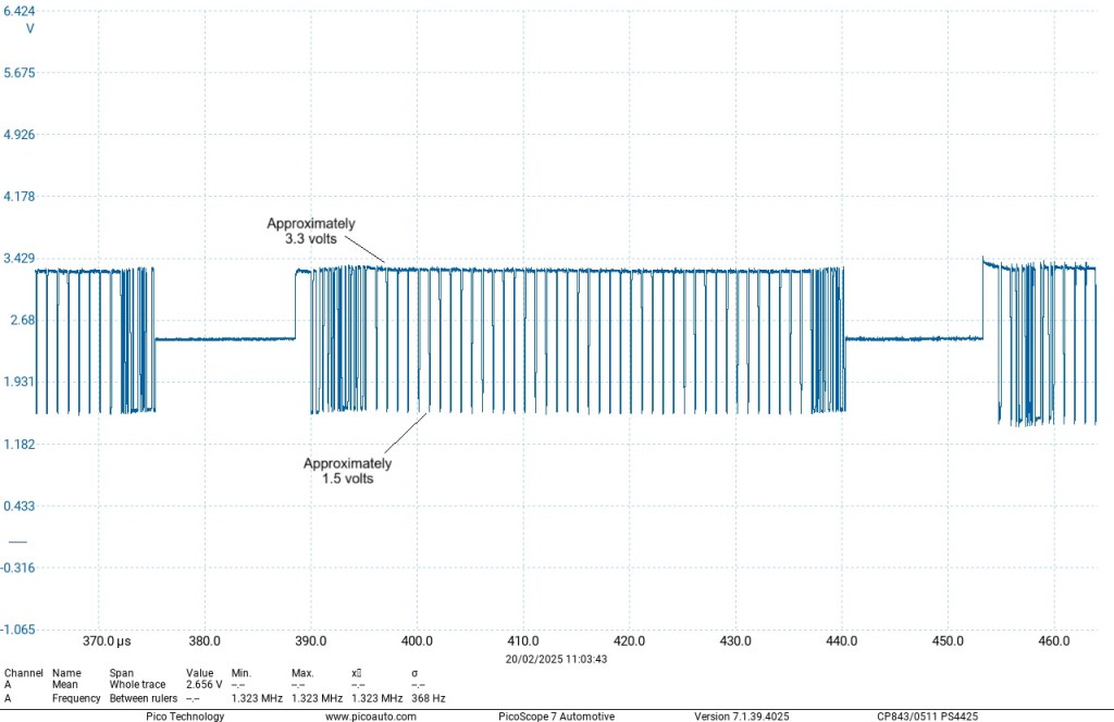
As you can see; quite a difference in the image quality. The average frequency of the regular CAN is around 500 kHz. The FlexRay frequency measured here is 1.3 MHz. That’s almost 3 times faster. (Note: CAN can run up to 1 MHz and FlexRay can run up to 10 MHz)
Below is a capture of the Low side bus.