The following image is from a 2018 1.2l turbo direct injection EB2 engine, (taken from a Peugeot).
This engine is fitted in multiple vehicles, including Peugeot, Citroen and Vauxhall.
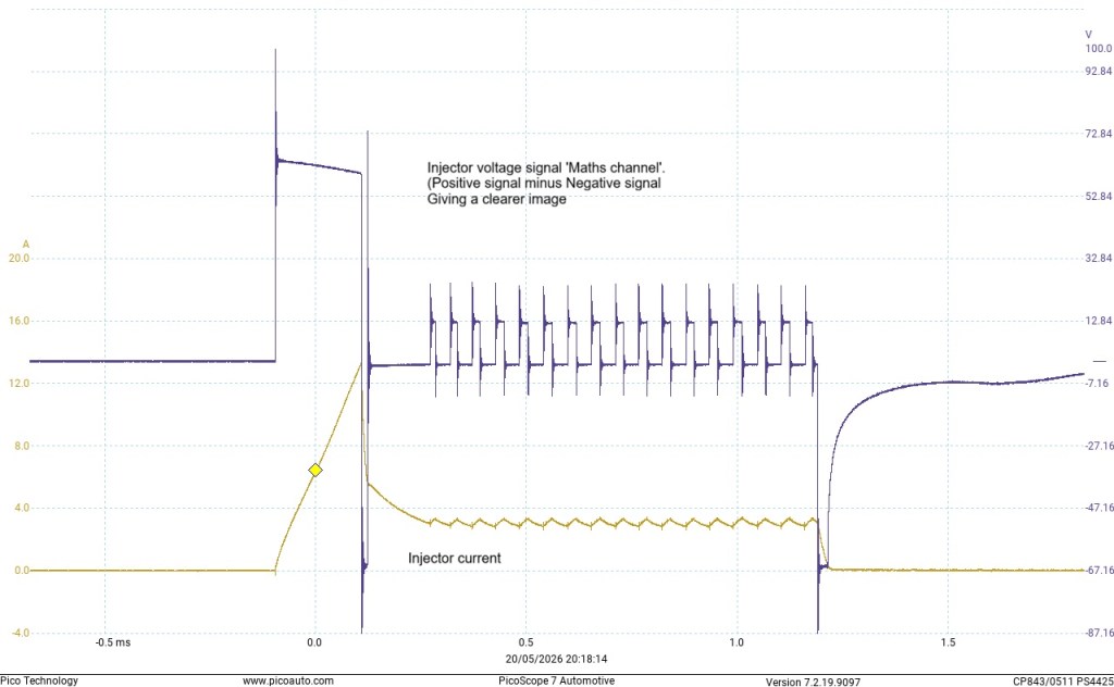
The following image is an edited ‘Maths channel’ image, which allows for a clearer image.
This waveform is of a standard or conventional ‘saturated switch’ petrol injector, fitted to a multi point (MPI) injection system. This is a good working sample.
You can see in the above image, how the injection duration is defined by the pulse width of the blue trace. It is, in this case, 2.9ms. However the duration the injector is physically and fully open is approximately 2ms, as defined by the 2 signatures from the combination of the current and voltage. In the case of the opening hump in the current waveform, it doesn’t mean that fuel is not being passed before the hump, but it does show when the pintle is fully open.
The following image is of a ‘Peak and hold’ Throttle body injection, (TBI), or single point injection. It was fitted to a 1994 Vauxhall Cavalier.
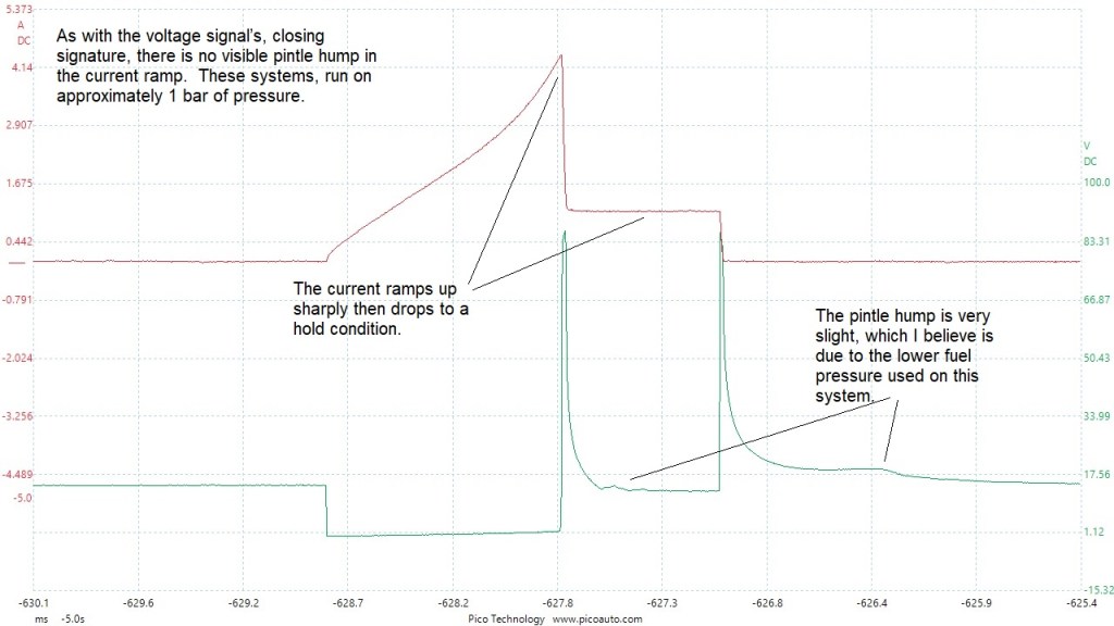
As can been seen in the waveform above, The TBI current is much higher than with the ‘saturated switch’ injector, but the duration is less for the maximum current. This means that the load on the output driver in the ECM is about the same as the MPI system. With regards to the pintle signature, typically the fuel pressure will be around 1 bar compared to the MPI system which will be around 2.5 to 4 bars. I think this maybe a contributory factor in the pintle hump detail or lack thereof, in the waveform.
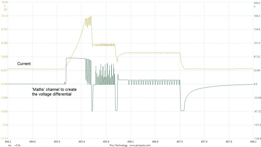
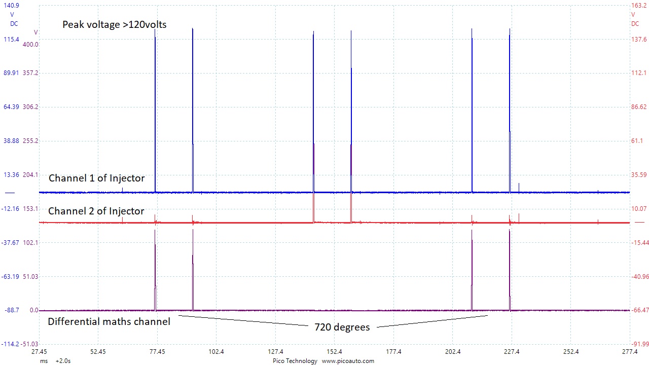
This capture is from a 2006 VW TFSI, direct injection turbo charged engine. This is a differential coupling and you can see it resembles the common rail diesel injector pattern. The control unit contains capacitors that provide the high voltage used to operate the injectors, usually 2 capacitors for a 4 cylinder engine.
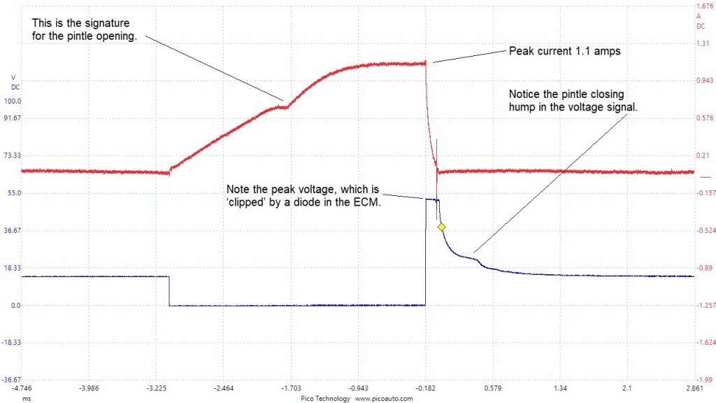
This waveform image shows the detail of a common, multipoint petrol injector, mounted in the inlet manifold. (Indirect injection or manifold injection). This was taken from a 2006 2.0 Mazda.
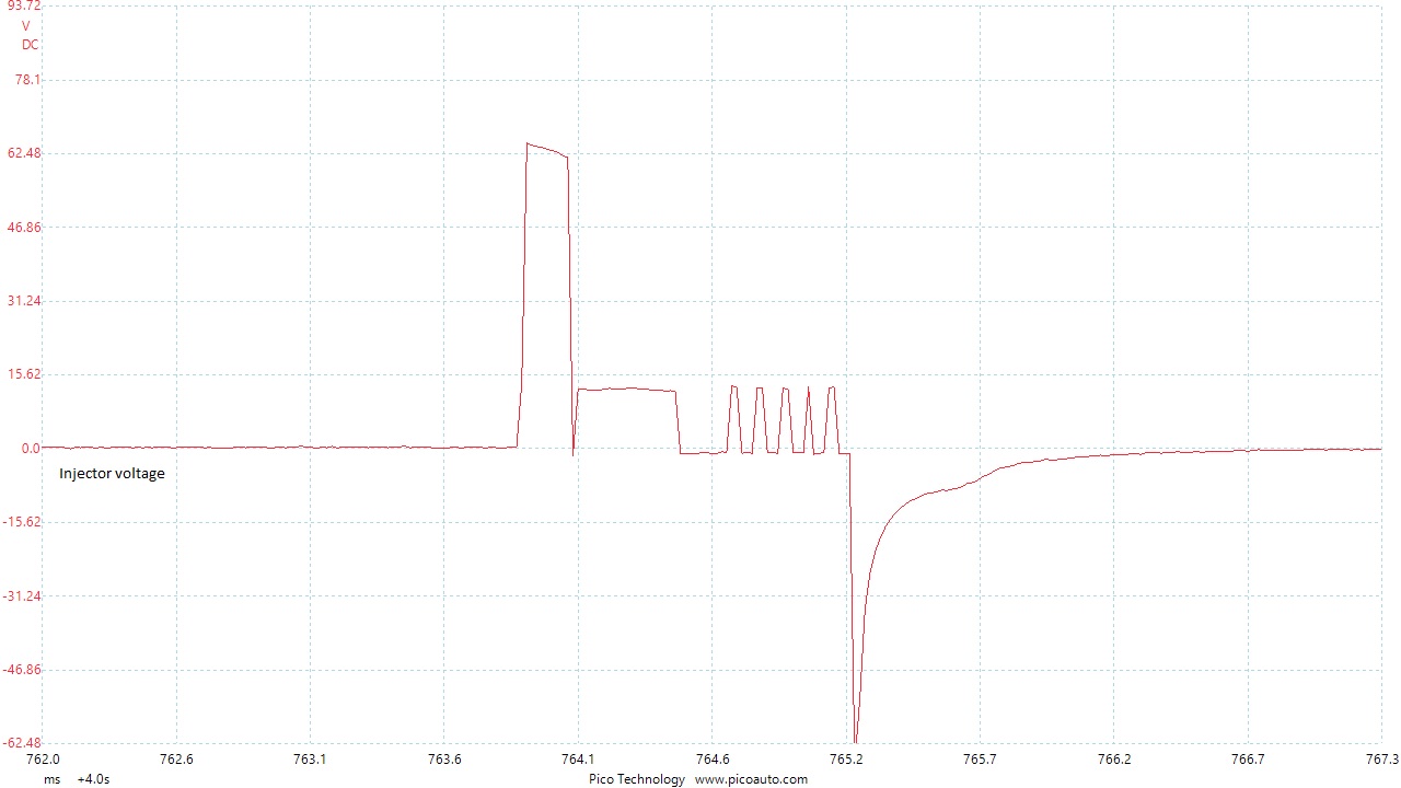
This next waveform set, show a sample taken from a direct injection petrol BMW (N43), which uses piezo injectors. The first image shows a full cycle of cylinder No.1. I have used a maths channel to show the actual injector opening signals, as the other voltage signals can be confusing. They are the ghost signals from the driver circuit in the ECU and completely normal. Unfortunately I was unable to get a current clamp in place to sample current. But, as you will see, I have managed to show what the current pattern would look like, from the ground side voltage drop.
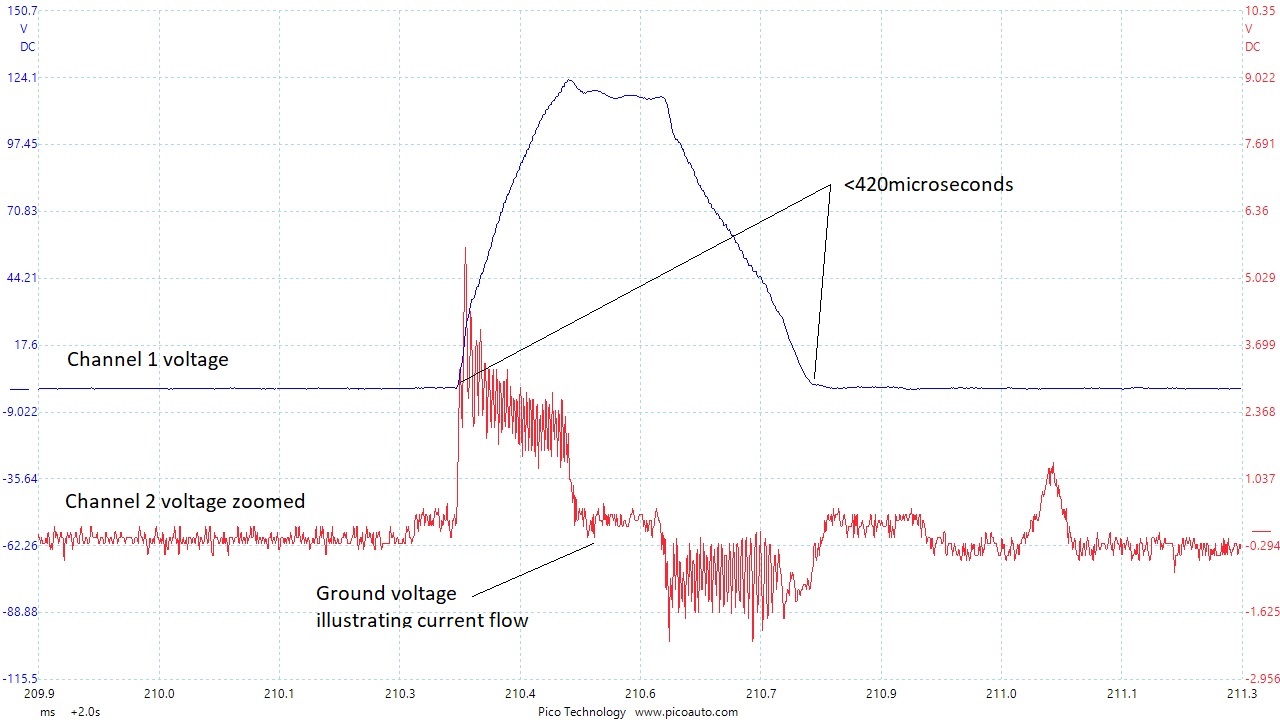
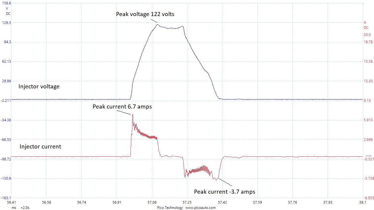
This next image is a capture of the same type of petrol injector as above, only this one has a current sample also. It plainly illustrates how the current signal mimics the volt-drop shown in the ground voltage signal above.
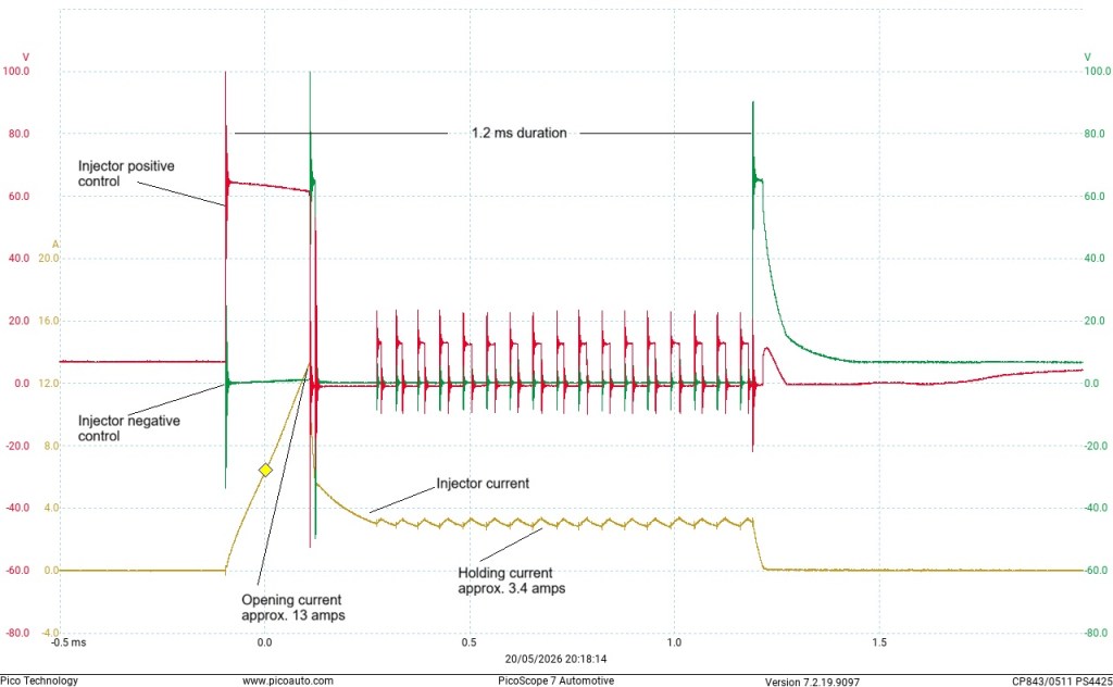
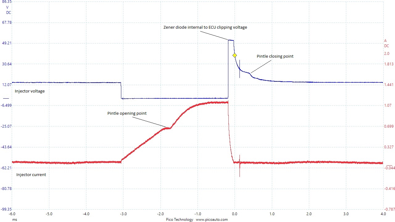
This image was taken from a 2016 Direct injection petrol engine, fitted in a Vauxhall Astra. It’s a 1.4 litre turbo with Delphi engine management.
The injectors are of the solenoid type.